
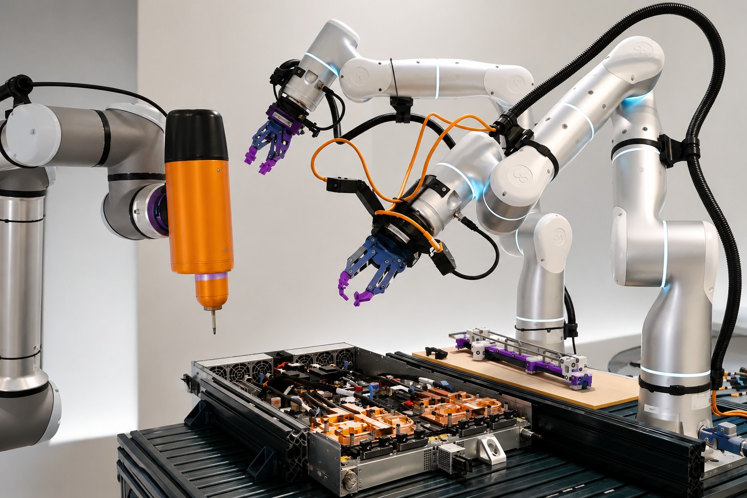
Two jobs, different constraints
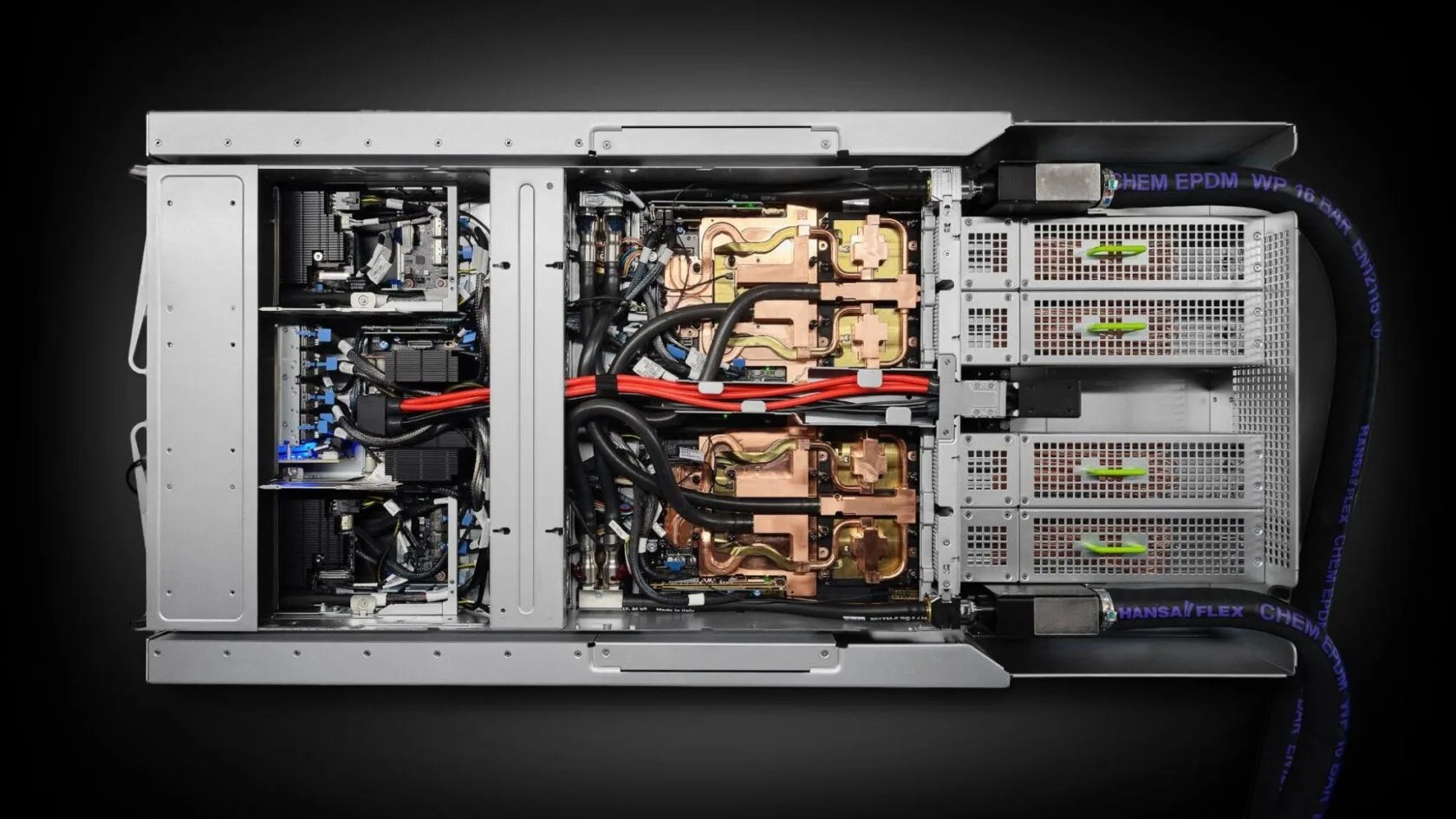
The tray assembly problem is difficult because the parts and their starting positions vary. Cables deform along their length, differ from one another and change with wear. The production volumes and changing designs also make rigid fixtures and tightly controlled automation a poor fit.
Manufacturers set a demanding target: at least 99.5% success, with each operation taking no more than twice as long as a skilled worker. Any accidental collision with the tray was unacceptable, because even minor damage could scrap the system.
For the busbar, the robot must place a heavy metal part and secure it with 16 screws. The team used a modular system rather than the end-to-end learning approach it had initially expected to need. It was easier to debug and tune, and its components could be split across robot arms.
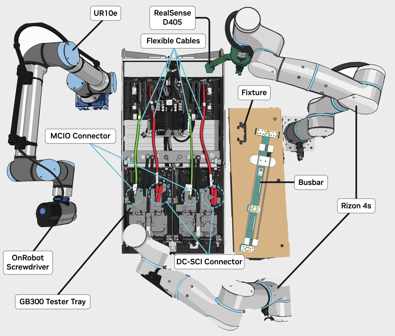
The work was divided among three manipulators:
The team used multiple camera views to reduce pose-estimation errors, a fast waypoint planner and a high-performance impedance controller for stable contact. It also slightly modified the busbar clamp so one arm could release it.
The busbar assembly succeeded more than 95% of the time. Placing the fixture and busbar met the time target, but screwdriving did not: the full cycle took 160 seconds against a 124-second target. Most remaining failures came from grasping or slipping during placement.
Source: developer.nvidia.com
Video 1. Skilled workers at a Foxconn factory performing busbar assembly
Source: developer.nvidia.com
Video 2. Workers performing multi-connector insertion
Source: developer.nvidia.com
The connector problem
Plugging in two large and two small connectors proved harder. The target was at least 99.5% success and no more than 72 seconds for all four cables. The team first used a segmentation model to find each cable, then grasped and lifted it to expose the connector. That simple method rarely failed.
Grasping the exposed connectors was another matter. They are small, have little texture and can sit differently at the end of each cable. I think this contrast is the most revealing part of the project: the robot could handle the cable with a conventional vision pipeline, but the tiny connector demanded a more specialized approach.
Source: developer.nvidia.com
Source: developer.nvidia.com
The team tried imitation learning with action-chunking transformers and diffusion policies, but success rates were low. These methods need large quantities of good training data, and the specialized cables could only be handled a limited number of times before deforming. The team calls this an “inverse bitter lesson”: in some physical tasks, collecting data at scale is not practical, so classical methods that use domain knowledge become attractive again.
NVIDIA Research and the robotics lab developed Deep Object Pose Estimation Revisited, or DOPER, to estimate the connectors’ poses. The model is first trained on synthetic images of a specific part, then refined using images of a 3D reconstruction of that part in real-world settings. DOPER gave the team fast, specialized pose estimates, letting one manipulator move a connector into a position where another could grasp it.
Figure 8. [Left] Videos of the first set of multi-purpose gripper fingers. These fingers are designed to accept pre-grasp pose deviations and guide parts into repeatable post-grasp poses. The first video shows gripper fingers grasping the small MCIO connector. The second video shows the same set of gripper fingers grasping the large DC-SCI connector. [Right] 3D CAD renderings of the multi-purpose gripper fingers with the DC-SCI and MCIO connectors, showing perspective and cross-section views. The finger geometry constrains connector motion during contact to produce repeatable post-grasp poses
Source: developer.nvidia.com
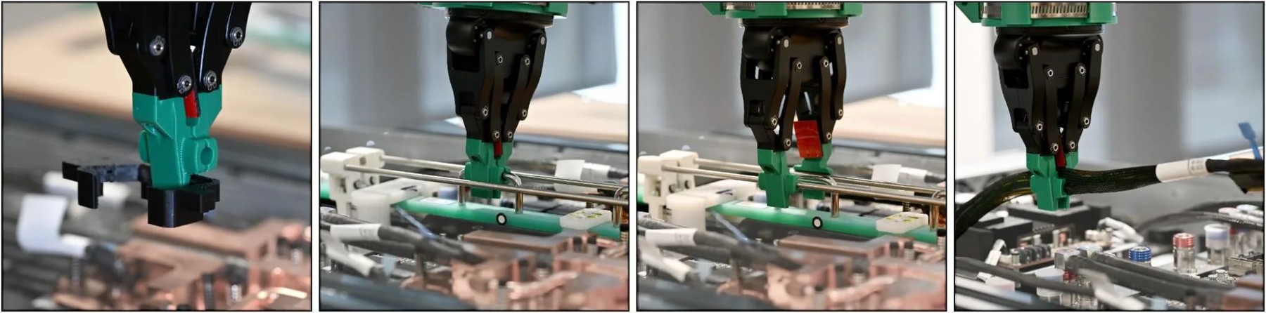
Figure 9. Second set of multi-purpose gripper fingers. These fingers are designed to grasp (from left to right) the fixture, the busbar handle, the release mechanism for the busbar clamp, and the cables
Source: developer.nvidia.com
The insertion step required a different tool again. The team trained reinforcement-learning policies in NVIDIA Isaac Lab and transferred them to real robots. Simulation worked better for the large connector than the small one; even a slight pose error could make a connector slide off the socket’s edge. The team then refined its SPARR method: a policy trained on simulated system state provides a starting point, while a real-world residual policy learns from force and torque readings.
The combined system could connect all four cables from start to finish, with 90–95% success. It took an average of 40 seconds per cable, and performance remained below the manufacturers’ requirements. Most remaining failures involved coordinating the manipulators during connector grasping.
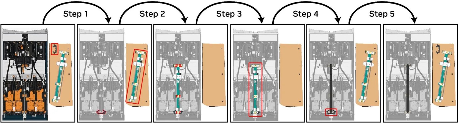
Figure 3. The five substeps of busbar assembly The key parts in each step are boxed in red
Source: developer.nvidia.com
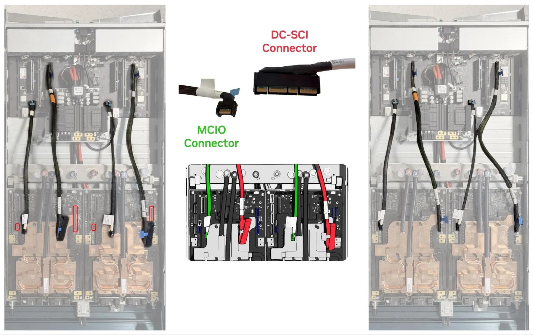
Figure 4. Initial conditions, connector types, and final state for multi-connector insertion. Target sockets are encircled in red on the left; MCIO connectors are highlighted in green, DC-SCI connectors in red
Source: developer.nvidia.com
![Figure 5. [Left] Sample image from the wrist-mounted RealSense D405 camera. [Right] SAM3 segmentations and extracted cable centerlines](https://dataist.ai/news/nvidias-gb300-robot-assembly-falls-short-of-factory-targets/fig_4.jpg)
Figure 5. [Left] Sample image from the wrist-mounted RealSense D405 camera. [Right] SAM3 segmentations and extracted cable centerlines
Source: developer.nvidia.com
![Figure 6. An exposed connector after its cable has been grasped and lifted. [Inset] View from a wrist-mounted RealSense D405 camera. The connector’s bounding box, keypoints, and 6D pose from DOPER are annotated](https://dataist.ai/news/nvidias-gb300-robot-assembly-falls-short-of-factory-targets/fig_5.jpg)
Figure 6. An exposed connector after its cable has been grasped and lifted. [Inset] View from a wrist-mounted RealSense D405 camera. The connector’s bounding box, keypoints, and 6D pose from DOPER are annotated
Source: developer.nvidia.com
Source: developer.nvidia.com
In simulation, policies for the DC-SCI and MCIO connectors are shown at different training stages.
Source: developer.nvidia.com
Video 3. A human demonstration of what our robotic solution should perform in busbar assembly and multi-connector insertion. These steps differ slightly from those performed by Foxconn workers (shown in Videos 1 and 2); a robotic solution doesn’t require a large protective bracket and can perform screwdriving in a single phase
Source: developer.nvidia.com
The factory is a different test
The results are promising, but they are not yet factory-ready. The busbar operation missed its cycle-time target; connector reliability was well short of the required 99.5%. And the team’s own production standard makes clear how much evidence remains: confirming a success probability of at least 99.5% with a one-sided 95% confidence bound requires at least 598 trials with no failures.
That test could consume hundreds of identical GB300 components, which themselves wear with use. I think the announcement is quiet about the hardest practical question: how to validate a system at production-level confidence without using up the parts it is meant to assemble.
NVIDIA’s proposed answer is to put imperfect robots into real operations under human supervision, record interventions and use the resulting production data to improve them. The approach resembles the gradual handoff from human oversight to autonomy described in the autonomous-vehicle industry. It is a sensible direction, but the article offers no results from a factory deployment.
The larger research point is less tidy than a case for end-to-end learning. Different parts of the job called for different methods: modular perception, planning and control for the busbar; specialized pose estimation for connector grasping; and reinforcement learning for insertion. Mechanical changes helped too. The team designed two sets of general-purpose gripper fingers that constrained how parts moved on contact, making grasping more repeatable without adding tactile sensors or extra recovery steps.
That mix matters because the parts, their geometry and their physical properties vary, while production cannot rely on endless retries. NVIDIA’s account is strongest when it treats methods as tools chosen for particular constraints. Its next test is whether that combination can meet production standards outside the lab—and do so without turning every new part into a new research project.
Video 4. Our busbar assembly solution. One Flexiv arm positions a camera for pose estimation. A second Flexiv arm inserts the limit fixture and busbar (with attached clamp). A UR arm uses an OnRobot Screwdriver to screw the busbar into the tray. The second Flexiv arm then removes the busbar clamp and the limit fixture
Source: developer.nvidia.com
Video 5. A subset of our robotics services
Source: developer.nvidia.com
Video 6. Example use-cases of TALO S
Source: developer.nvidia.com
Video 7. Repeated deployment of our cable-grasping approach
Source: developer.nvidia.com
Video 8. Repeated deployment of our connector-grasping approach
Source: developer.nvidia.com
Source: developer.nvidia.com
Source: developer.nvidia.com
Video 13. Repeated deployment of our connector-insertion approach. Actions from a base policy trained in simulation are composed with actions from a residual policy trained in the real world
Source: developer.nvidia.com
Video 14. Our multi-connector insertion solution. One Flexiv arm lifts the target cable to expose its connector and reorients it into a pose that is reachable by a second Flexiv arm. The second arm grasps the connector and deploys a learned policy to insert the connector into its socket. This sequence is repeated for each remaining cable
Source: developer.nvidia.com
Video 15. Recent experiments with GPT-6 Astra in a learned world model. Astra possesses impressive spatial understanding and can control robots in world models, enabling roboticists to collect large amounts of valuable data
Source: developer.nvidia.com
Daily AI news
Every day we pick what actually matters in AI and explain it plainly — no hype, no filler. Subscribe if you want to follow where the industry is going.
Only what matters — every day
Follow on X